- 您现在的位置:买卖IC网 > Sheet目录1994 > DS2404B (Maxim Integrated Products)IC ECONORAM TIMECHIP 5.5V 16SSOP
DS2404
3 of 29
4) skip ROM or 5) search interrupt. After a ROM function sequence has been successfully executed, the
memory functions are accessible and the master may then provide any one of the four memory function
commands (Figure 6).
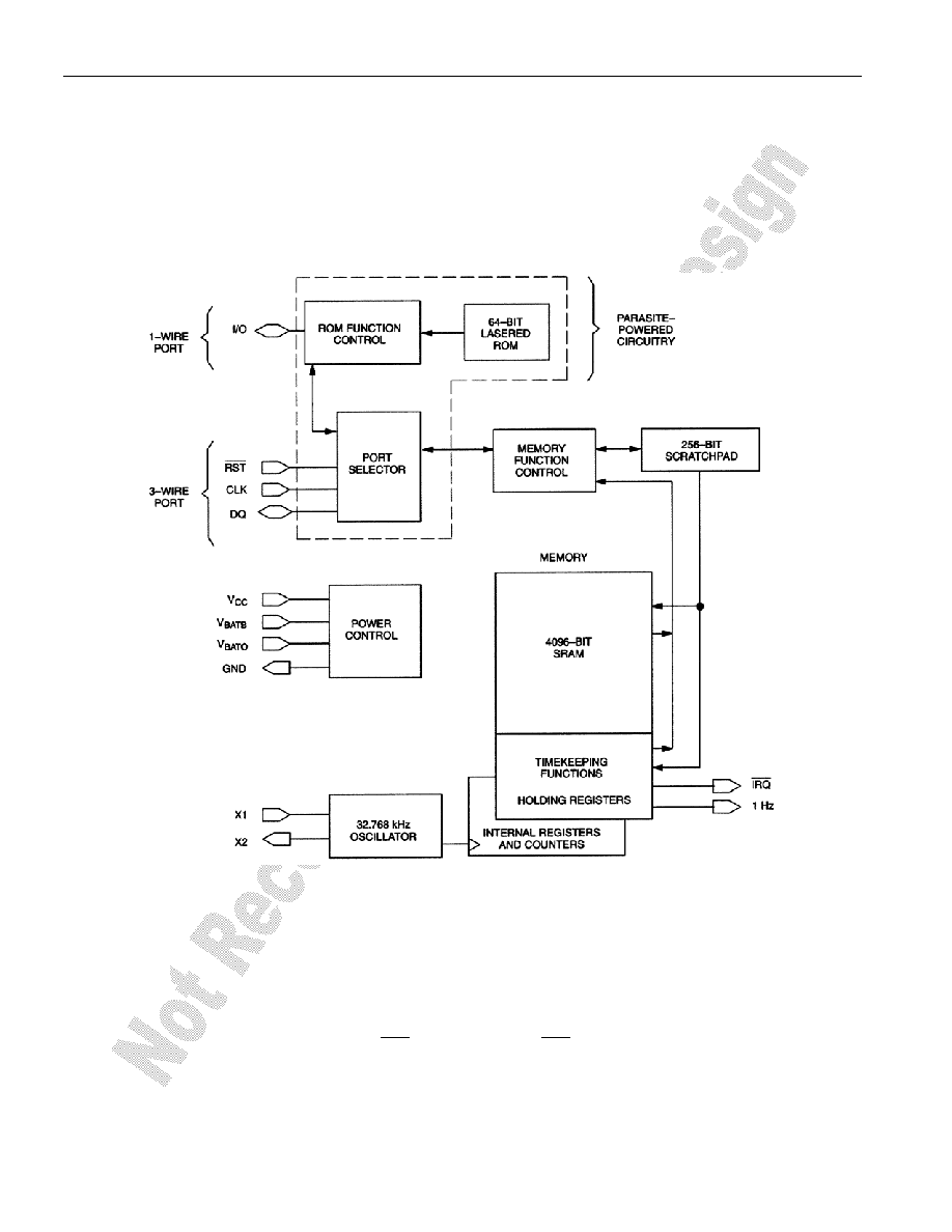
The “Power Control” section provides for two basic power configurations: battery operate mode and VCC
operate mode. The battery operate mode utilizes one supply connected to VBATO. The VCC operate mode
may utilize two supplies; the primary supply connects to VCC and a backup supply connects to VBATB.
DS2404 BLOCK DIAGRAM Figure 1
COMMUNICATION PORTS
Two communication ports are provided: a 1-Wire and a 3-wire port. The advantages of using the 1-Wire
port are as follows: 1) provides access to the 64-bit lasered ROM, 2) consist of a single communication
signal (I/O), and 3) multiple devices may be connected to the 1-Wire bus. The 1-Wire bus has a
maximum data rate of 16.3kbits/s and requires one 5k
Ω external pull-up.
The 3-wire port consists of three signals: RST , CLK, and DQ. RST is an enable input, DQ is bidirectional
serial data, and the CLK input is used to clock in or out the serial data. The advantages of using the
3-wire port are 1) high data transfer rate (2MHz), 2) simple timing, and 3) no external pull-up required.
发布紧急采购,3分钟左右您将得到回复。
相关PDF资料
DS2415P+T&R
IC TIME CHIP 1-WIRE 6-TSOC
DS2417X/T&R
IC TIMECHIP W/INTRPT 1WIRE CSP
DS26502LN+
IC T1/E1/J1 64KCC ELEMENT 64LQFP
DS26503LN+
IC T1/E1/J1 BITS ELEMENT 64-LQFP
DS3105LN+
IC TIMING LINE CARD 64-LQFP
DS3106LN+
IC TIMING LINE CARD 64-LQFP
DS3231MZ+
IC RTC I2C 8SOIC
DS3231SN#T&R
IC RTC W/TCXO 16-SOIC
相关代理商/技术参数
DS2404B/T&R
制造商:Maxim Integrated Products 功能描述:ECONORAM/TIME, SSOP16-TRL (GENERIC) - Tape and Reel
DS2404B+
制造商:Maxim Integrated Products 功能描述:REAL TIME CLOCK SERL 512BYTE 16SSOP - Rail/Tube
DS2404B+T&R
制造商:Maxim Integrated Products 功能描述:REAL TIME CLOCK SERL 512BYTE 16SSOP - Tape and Reel
DS2404FP000
制造商:Thomas & Betts 功能描述:200A,CON,3P4W,MG,404,3P480V
DS2404FP000/DF2029
制造商:Thomas & Betts 功能描述:RS DS2404FP000/DF2029 200A,CON,3P4W
DS2404FP000/DF2032
制造商:Thomas & Betts 功能描述:200A,CON,3P4W,MG,404,3P480V,DF2032
DS2404FP00K
制造商:Thomas & Betts 功能描述:200A,CON,3P4W,MG,404,00K,3P480V
DS2404FPOOO/DF2029
制造商:Thomas & Betts 功能描述:RS DS2404FPOOO/DF2029 200A,CON,3P4W